Juniper - Day One: This Week - Deploying MPLS Layer 3 VPN
Files for this lab can be found here, same deal as the Deploying MPLS Introduction post.
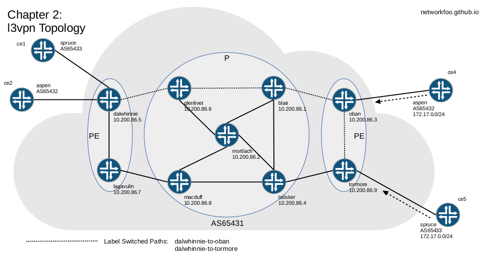
To get Layer 3 VPN working, fundamentally it is all about Virtual Routing & Forwarding Route Instances.
First up, let’s add MP-BGP to all three of the PE routers that have CE routers connected on the above topology:
protocols {
    bgp {
        family inet {
            any;
         }
         family inet-vpn {
             any;
         }
    }
}
While doing this, it a good time to make sure that you have the necessary neighbor directives for all your necessary iBGP peers.
Next, we will configure VRF’s. Start with dalwhinnie, you’ll need to add:
routing-instances {
    spruce {
        instance-type vrf;
        interface em3.0;
        route-distinguisher 192.168.90.2:30;
        vrf-target target:100:300;
        vrf-table-label;
        protocols {
            bgp {
                group ce1 {
                    peer-as 65433;
                    neighbor 192.168.90.2;
                }
            }
        }
    }
    aspen {
        instance-type vrf;
        interface em4.0;
        route-distinguisher 192.168.90.6:20;
        vrf-target target:100:200;
        vrf-table-label;
        protocols {
            bgp {
                group ce2 {
                    peer-as 65432;
                    neighbor 192.168.90.6;
                }
            }
        }
    }
}
Note: For the keen observer you will have noticed I have not used the interface ge-0/0/1.800 and .801, as in the Day One book. It is just the way I did it… when venturing into uncharted territories I try to keep things as simple as possible and I thought adding IP Aliases to the mix would just confuse things.
Next, router oban also requires config for the peered CE4 router as well as tormore for the peered CE5 router.
Route Distinguishers
You have already done everything you need to get route-distiguishers working, with that simple line route-distinguisher 192.168.90.2:30; under the VRF configs.
Route Targets
Here needs a little more attention to detail. We need to have our CE Routers mark the BGP routes they send with thier respective VRF name and Target:
on CE4 and CE5*:
policy-options {
    policy-statement to-AS65431 {
        term match-to-AS65431 {
            from {
                route-filter 172.17.0.0/24 exact;
            }
            then {
                community add spruce;
                accept;
            }
        }
    }
    community spruce members target:100:300;
}
*of course substituting VRF name and Target where necessary.
Layer 3 VPN Verification
Hey? … Verification already? … whoaa, but we have not even fired up routers CE1 & CE2, let alone configured them!!! Meh… we don’t need to. Let’s just get on with the verification and afterwards (at the very end), if you like, you can load the config files to to do further verification.
Perusing the show route - detail output for the 172.17.0/24 route shows us that all our work has not been in vain. Exactly as in the Day One book, note the bold text:
networkfoo@dalwhinnie> show route 172.17.0.0/24 detail

aspen.inet.0: 5 destinations, 5 routes (5 active, 0 holddown, 0 hidden)
172.17.0.0/24 (1 entry, 1 announced)
        *BGP    Preference: 170/-101
                Route Distinguisher: 192.168.90.14:20
		. . .
		. . .
                Communities: target:100:200
                Import Accepted
                VPN Label: 16
                Localpref: 100
                Router ID: 10.200.86.3
                Primary Routing Table bgp.l3vpn.0

spruce.inet.0: 5 destinations, 5 routes (5 active, 0 holddown, 0 hidden)

172.17.0.0/24 (1 entry, 1 announced)
        *BGP    Preference: 170/-101
                Route Distinguisher: 192.168.90.18:30
		. . .
		. . .
                Communities: target:100:300
                Import Accepted
                VPN Label: 16
                Localpref: 100
                Router ID: 10.200.86.9
                Primary Routing Table bgp.l3vpn.0

bgp.l3vpn.0: 6 destinations, 6 routes (6 active, 0 holddown, 0 hidden)

192.168.90.14:20:172.17.0.0/24 (1 entry, 0 announced)
        *BGP    Preference: 170/-101
                Route Distinguisher: 192.168.90.14:20
		. . .
		. . .
                Communities: target:100:200
                Import Accepted
                VPN Label: 16
                Localpref: 100
                Router ID: 10.200.86.3
                Secondary Tables: aspen.inet.0

192.168.90.18:30:172.17.0.0/24 (1 entry, 0 announced)
        *BGP    Preference: 170/-101
                Route Distinguisher: 192.168.90.18:30
		. . .
		. . .
                Communities: target:100:300
                Import Accepted
                VPN Label: 16
                Localpref: 100
                Router ID: 10.200.86.9
                Secondary Tables: spruce.inet.0
Traceroutes & Layer 3 VPN’s
Running a traceroute to confirm our path is of little use, as the P routers do not have a route back to the CE routers and this will show as splats in traceroute. Not exactly what we want.
networkfoo@dalwhinnie> traceroute routing-instance spruce 172.17.0.1
traceroute to 172.17.0.1 (172.17.0.1), 30 hops max, 40 byte packets
 1  * * *
 2  * * *
 3  * * *
 4  172.17.0.1 (172.17.0.1)  1.195 ms  0.792 ms  0.825 ms
We can correct this by issuing icmp-tunneling on all our MPLS routers through the network:
networkfoo@dalwhinnie# set protocols mpls icmp-tunneling
Now we get the expected response:
networkfoo@dalwhinnie> traceroute routing-instance spruce 172.17.0.1
traceroute to 172.17.0.1 (172.17.0.1), 30 hops max, 40 byte packets
 1  192.168.86.5 (192.168.86.5)  1.092 ms  0.624 ms  0.725 ms
     MPLS Label=300720 CoS=0 TTL=1 S=0
     MPLS Label=16 CoS=0 TTL=1 S=1
 2  192.168.86.9 (192.168.86.9)  0.580 ms  0.634 ms  0.661 ms
     MPLS Label=300912 CoS=0 TTL=1 S=0
     MPLS Label=16 CoS=0 TTL=2 S=1
 3  192.168.86.25 (192.168.86.25)  0.554 ms  0.569 ms  0.639 ms
     MPLS Label=300752 CoS=0 TTL=1 S=0
     MPLS Label=16 CoS=0 TTL=3 S=1
 4  172.17.0.1 (172.17.0.1)  0.888 ms  0.780 ms  0.787 ms
Depending on your circumstances you may not desire to show all this information. So we can effectively hide the MPLS path, should we want to, with the no-decrement-ttl directive. This is only necessary on the ingress router. Also, we can disable icmp-tunneling but do not need to.
networkfoo@dalwhinnie# set protocols mpls no-decrement-ttl
Follows is our MPLS hidden traceroute:
networkfoo@dalwhinnie> traceroute routing-instance spruce 172.17.0.1
traceroute to 172.17.0.1 (172.17.0.1), 30 hops max, 40 byte packets
 1  192.168.90.17 (192.168.90.17)  1.098 ms  0.589 ms  0.800 ms
 2  172.17.0.1 (172.17.0.1)  0.923 ms  0.791 ms  0.822 ms
Conclusion
So as you see we have proven working l3vpn connectivity. However we still have not set up CE1 & CE2 routers. I have included a ce1-l3vpn.cfg in the usual place to set up the Customer Edge router should you wish to conduct more tests.
I hope that this has helped and provided a base for further investigations.